Sunday, February 28, 2016

Connecting multiple LCD displays to an Arduino

The LCD Display

The LCD Display based on Hitachi HD (or equivalent) have been around for many years. They are a very popular way to display information on any microcontroller circuit.


They are available from many manufacturer and are in various display size. The usual size is 16x2 characters but you can find variants in 40x2 characters or 16x4 characters.

The display includes the full circuitry to drive the display and interface with the microcontroller.

Interfacing with the Arduino

 Interfacing with the Arduino is very straight forward and very well documented in www.arduino.cc/en/Tutorial/HelloWorld

The schematic is quite simple:


We can limit the number of wires used on the Arduino by using a 4 bits interface instead of 8 bits and hardwiring the R/W pin to VSS since we don't need to read back information for the display.

This means that the interface is reduced to 4 data bits (DB4...DB7) and the 2 control wires: RS and E.
RS is used to select the register where the data shall be written (one register is used to display text and the other one is used to control the display behaviour) . The E wire is used to perform the actual data write operation.

To access the LCD display from the Arduino sketch we use an object of the LiquidCrystal class (for the standard Arduino library LiquidCrystal.h) by creating it with the correct pin assignation:

  lcd(12, 10, 5, 4, 3, 2);

Warning: When wiring the display, check carefully the manufacturer datasheet to find the correct pinout. Every manufacturer agrees that there are 14 pins to control the LCD + 2 pins to control the backlight but the exact pin assignation varies slightly from a manufacturer to another.

Multiple Displays


Now we want to connect one (or more) additional displays to the Arduino

As explained above the LCD display takes the data into account only when the E pin is activated. This means that you can connect all the displays signals in parallel on the Arduino digital outputs as long as you keep the E signals separated.

In the schematics below I have used digital output D10 to control E signal of LCD1  and output D11 to control E signal of LCD2

The Software

The Arduino sketch to control multiple displays is very similar to the one used to control one display.

You simply have to create one object of the LiquidCrystal class for each display. I have found that the easiest way to do it is to store them in array by using the following code:
 
LiquidCrystal lcd[2]={LiquidCrystal(12, 11, 5, 4, 3, 2), LiquidCrystal(12, 10, 5, 4, 3, 2)};


This allows to easily select on which display to print (or to send any command) as shown in the very simple "Hello World" example below.

warning, since arrays begin at index zero, the 2 LCD displays shall be numbered zero and on1 (instead of one and two).

/*
This sketch prints "Hello World!" on 2 LCD displays
The circuit:
* LCD RS pin to digital pin 12
* LCD Enable pin to digital pin 11 for LCD1 pin 10 for LCD 0
* LCD D4 pin to digital pin 5
* LCD D5 pin to digital pin 4
* LCD D6 pin to digital pin 3
* LCD D7 pin to digital pin 2
* LCD R/W pin to ground
* LCD VSS pin to ground
* LCD VCC pin to 5V
* 10K pot
* ends to +5V and ground
* wiper to LCD VO pin
*/

// Directly based on the Arduino example LiquidCrystal HelloWorld
#include <LiquidCrystal.h>

LiquidCrystal lcd[2] = { LiquidCrystal(12, 11, 5, 4, 3, 2),LiquidCrystal(12, 10, 5, 4, 3, 2) };

void setup() {
// set up the LCD's number of columns and rows:
lcd[0].begin(16, 2);
lcd[1].begin(16, 2);
lcd[0].setCursor(0, 0);

lcd[0].print("Hello");
lcd[1].setCursor(0, 0);
lcd[1].print("World!");
}

void loop() {
}

Monday, November 30, 2015

GPIO pins allocation under windows 10 IOT build on Raspberry PI

The Windows 10 IOT documentation https://ms-iot.github.io/
indicates that only the following pins are available 4,5,6,12,13,16,17,18,19,20,21,22,23,24,25,26,27 for GPIO.

If you wonder why so many pins are not usable as GPIO. This is because
  • GPIO 2, and 3 are reserved for I2C interface
  • GPIO 7,8,9,10,11 are reserved for SPIO interface
  • GPIO 14,15 are reserved for UART interface.


Note that 35 and 47 are also available but they drive LEDs soldered on the board and not pins on the GPIO connector.

If you are still using Windows10 IOT build 10.0.10240 you must know that for some unknown reasons the Raspberry PI GPIO pins 17, 19, 20, 21 are not usable. I think this is a very good reason to update to build 10.0.10556.


Program To list all the available GPIOs

 
I have developed a small program that list all the available GPIOs.
 
The XAML is the following
 

<Page
x:Class="CountGPIO.MainPage"
xmlns="http://schemas.microsoft.com/winfx/2006/xaml/presentation"
xmlns:x="http://schemas.microsoft.com/winfx/2006/xaml"
xmlns:local="using:CountGPIO"
xmlns:d="http://schemas.microsoft.com/expression/blend/2008"
xmlns:mc="http://schemas.openxmlformats.org/markup-compatibility/2006"
mc:Ignorable="d">
<Grid Background="{ThemeResource ApplicationPageBackgroundThemeBrush}">
<TextBlock x:Name="TextblockOutput" HorizontalAlignment="Center" VerticalAlignment="Center" />
</Grid>
</Page>


And the C# code associated
 

using System;
using Windows.Devices.Gpio;
using Windows.UI.Xaml.Controls;
namespace CountGPIO
{
  public sealed partial class MainPage : Page

  {
    private GpioController gpio;

    public MainPage()
    {
    this.InitializeComponent();

    gpio = GpioController.GetDefault();
    this.TextblockOutput.Text = "List of Supported GPIO pins:" +  Environment.NewLine;
    for (int port = 0; port < 64; port++)
     {
     try

      {
      gpio.OpenPin(port);
      this.TextblockOutput.Text += "GPIO Pin: " + port.ToString() + " is OK" + Environment.NewLine;

      }
     catch (Exception)

      { }
     }
    }
  }
}


Sunday, November 15, 2015

How to use a PC To Connect a Raspberry PI to a WIFI network


Introduction

 
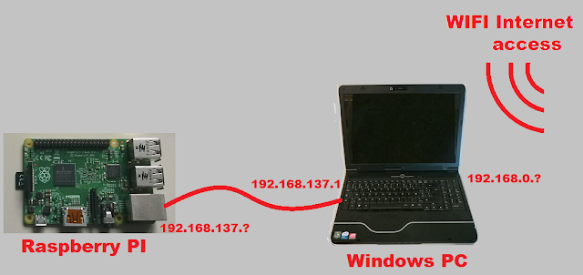
The problem is the following : I am using have a standard Raspberry PI (i.e. without any WIFI interface) at a location where the only way to access the Internet is the WIFI. Is it possible to use my portable PC running Windows as a router to connect the Raspberry PI to the Internet ?


The answer is YES and it is very easy


Step1: Activate ICS

Activate the ICS on the WIFI connection of the Windows computer. The ICS (Internet Connection Sharing) allows other computers to use the WIFI connection of the Windows computer.
This is done in the network control panel (you may reach it by using the command)
control ncpa.cpl
Then select properties on the WIFI network


And then activate the sharing of the the WIFI connection

Once this is done any computer connected to the PC ethernet port shall receive via DHCP an IP address in the 192.168.137.X network (note the PC is located at 192.168.137.1)


Step2 Connect the Raspberry PI to the PC


Connect the Raspberry PI with a standard Ethernet cable equipped with standard RJ45 connectors). You don't even need a crossed cable because the Raspberry PI support auto MDI-X (which means that the Raspberry PI will detect that a crossed cable is needed and automatically preform the « cross » internally) .
 
Now everything is done and your raspberry PI can access the Internet. But If You don't have keyboard and display connected to it you need to know which IP address the Windows PC DHCP has given to it.
 

Step 3 retrieve the Raspberry PI IP address

The simplest way to obtain this address is to query the ARP table. Start a Windows command prompt (if you don't know how to do it just press WINDOWS+R and type cmp ENTER)
and type the following command
arp -a -N 192.168.137.1
This will give you a reply that looks like that
 
In this list you see that the Rasberry PI has been granted the addres 192.168.137.55
 
Note : the 192,168,137,255, all the 224.x.x.x and the 239.255.255.250 addresses are all multicast addresses (we don't care about them)
You can now connect to you Rasberry PI via SSH and from the Raspberry PI communicate with the Internet.


Sunday, October 18, 2015

How to connect a PC to the Arduino Yun

Introduction


The Arduino Yun board is a relatively new member of the Arduino family.
 

It is similar to a Leonardo board ( i.e. An Arduino board with a Atmega32 processor) except that it has an additional processor (Atheros AR9331) running Linux (OpenWRT) , a microSD disk connector and many additional interfaces.


The Arduino Yun has many interfaces (not counting the usual Arduino connectors). There is a USB device micro type B connector, there is a USB host (Type A Connector). There is a wired Ethernet and there is also a possibility to connect via Wifi.
 

The USB Device Connector


This connector is the « standard » connector that we are used to see on every Arduino board except that it is a micro connector (like the one found on a smart phone) instead of a standard Type B connector.

As on an ordinary Arduino UNO you can use this connector to power the Arduino Yun board.
From the PC connected to the Yun board, this USB port appears as a standard COM port


As usual with Arduino boards, you may use this COM port to transfer a compiled sketch to the board and, a running sketch may use it to communicate using the well known serial class www.arduino.cc/en/Reference/Serial


The USB Host connector


This is a full size type A connector for connecting devices like USB keyboards, or mouse to the Yun. I have not yet experimented with it So I cannot say much about it. Just note that this port is connected to the Atheros AR9331 so it is controlled from LINUX. Which does not mean that the Atmega processor cannot acces it indirectly by going through the bridge that connects the 2 processors together.
 

The Wired Ethernet


Note: when using the Ethernet connection, don't forget to power your Yun board (if you don't use PoE) either via the USB micro connector or via the Vin pin (be careful with polarity an voltage).
Once the board is connected you need to know its IP address. The easiest way is to ask to your DHCP server/router the list of connected devices.
But you can also retrieve et IP address with this simple sketch (that you will have to upload via USB).
 

#include <Process.h>
void setup() {
// Initialize Bridge
Bridge.begin();
// Initialize Serial
Serial.begin(9600);
// Wait until a Serial Monitor is connected.
while (!Serial);
Process p; 
p.begin("ifconfig");
p.addParameter("-a"); // -a list all IP ports. Replace it by eth1 if you only
// want the wired Ethernet
p.run(); // Run the process and wait for its termination
while (p.available()>0) {
char c = p.read();
Serial.print(c);
}
Serial.flush();
}
void loop() {
//do nothing
}

The script result lista all the IP adresses used by the Yun board.


Note: Arduino Yun assigns the wired ethernet to eth1 and not eth0.


You can then connect to the Arduino Yun using any web browser


The password is « arduino »

An arduino sketch has no acces direct to the Ethernet port. To get acces to it You need to use the « bridge » object.


You may connect to the Linux terminal running on the Atheros AR9331 by using a ssh connection (on windows, the most popular ssh terminal is Putty (available on http://www.putty.org/)


The login is root and the default password is « arduino »

 
This gives you access to a surprisingly complete and powerful Linux computer.
It is possible to upload the sketch using the Wired Ethernet. To do that you need to install the « Bonjour » service and open the UDP port 5353 in your firewall. I have not tried it because I am happy with the USB transfer and I already have much too many services running on my PC.
 

 The Wifi

The Arduino YUN is by default a Wifi access point (i.e. a hotspot) This means that it creates a network on which you can connect your computer.
This is useful to reach the newly bought Yun board wifi but you will probably want to reconfigure it as a wireless adapter that connects to your Wifi network.
To do that connect your computer or any Wifi capable terminal (even a smartphone is ok) to the Yun Wifi network.

Use a browser to access the Yun board (it's address is 192.168.240.1)
The password is « arduino »
you can then configure the Wifi port so that it connects to your network

Once it is done the Wifi behave as the wired Ethernet (see explanation above)
Note : it is possible to turn off the Wifi. You may want to do that for security reasons. The code to execute to turn off the Wifi is quite complex. It is available is https://gist.github.com/sgk/6641198

Thursday, September 10, 2015

Creating A C# Desktop Program That Must Run With Administrator Privilege

The problem

Sometimes you want that your program requires to run with "administrator" privilege. For instance, if your program needs to listen to the TCP port 80.

This means that you would like to have this kind of message to appear at program start to request the user to grant the program elevated privilege.

The solution

It is possible to specify in Visual Studio to specify that an executable must be run with administrator privileges.

To do that you need to perform the 2 following steps:
  1. Add to the solution an "app.manifest" file

    The app.manifest is added to your solution
  2. Modify this file to set the correct value to requestedExectionLevel:
 

 <requestedExecutionLevel level="requireAdministrator" uiAccess="false" />


Note: When you try to debug such program inside the Visual studio environment, The visual studio shall detect that the administrator privileges are needed and request you to restart Visual studio in administrator mode.

Sunday, February 16, 2014

How to avoid the Exception "A cycle occurred while laying out the GUI." in a Windows store APP


The Observed Problem

Sometimes the exception "A cycle occurred while laying out the GUI." occurs in Windows 8 store application in an unpredicatble way. This can be very frustrating especially when the problem is observed only on some computers and not on others .

Note that when this occurs on a released and deployed Application the Application terminates silently without indicating any error message.

The explanation

The reason for this exception is in fact very simple: as the description says, we have an endless loop in the layout of the GUI. I have found that this nearly always occurs in the SizeChanged event handler.

  
 border.SizeChanged += _SizeChanged;  
 

What can be puzzling is that this can occur even if the SizeChanged Handler does something that should not trigger any endless loop. Example

  
 private  void _SizeChanged(object sender,
                     Windows.UI.Xaml.SizeChangedEventArgs e)
        {
            if (e.NewSize.Width < 150)
            {
                (border.Child as TextBlock).FontSize = 40;   
            }
            else
            {
                (border.Child as TextBlock).FontSize = 80;   
            }
        }
    }
 

Theoretically, the above code should never trigger an endless loop. But this is not the case. For some graphic résolutions, this method triggers endless calls to the _SizeChanged event Handler.

The work around

There is a simple way to make sure that the SizeChanged event is not called endlessly: ignore the event when it is called for nothing. Detecting useless SizeChanged events can easily be done by comparing the old size and the new size; if they are identical then the SizeChanged event was called for nothing and it can safely be ignored.

 
 if (e.PreviousSize != e.NewSize)   
 

Example: to prevent any risk of endless loop we should update the the following code to make it look like this:

  
 private  void _SizeChanged(object sender, 
                     Windows.UI.Xaml.SizeChangedEventArgs e)
        {
            if (e.PreviousSize != e.NewSize)
            {
                if (e.NewSize.Width < 150)
                {
                    (border.Child as TextBlock).FontSize = 40;   
                }
                else
                {
                    (border.Child as TextBlock).FontSize = 80;   
                }
            }
        }

Sunday, September 8, 2013

Reading Text from an embedded file in a WinRT application

When you want to provide data to a WinRT application (a.k.a. Windows Store App) it is sometimes useful to embed a file in your application package. This file may for instance contain help information, initial user settings, sample data...

To do that you need
  1. to include the file in the project
  2. to read the data
Let's make an example using a text file.
To include the text file in the application, just add the text file to the solution

Note that I have created a folder to put my text files .This avoid cluttering the project with too many files.

It is important to correctly select the build action Content to ensure that the file shall effectively be embedded in the application file.

Now that the file is included in the application package we must get access to it.
The code below shows how to read the whole text file and display its first two lines in textblocks
        protected async override void OnNavigatedTo(NavigationEventArgs e)
        {
            //retrieve the text file content
            Uri uri = new Uri("ms-appx:///MyTextFiles/MyTextFile1.txt");
            StorageFile file =
                await StorageFile.GetFileFromApplicationUriAsync(uri);
            IList<String> lines = await FileIO.ReadLinesAsync(file);

            //use the retrieved data
            TextBlock1.Text = lines[0];
            TextBlock2.Text = lines[1];
        }

Note the usage of an URI instead of a path to identify the file. Embedded files cannot be accessed using a file path.

Note also the very strange URI syntax with a triple slash ms-appx:///

Obviously, the same technique can be used to embed other things than text files. You could embed images, sounds or binary data.
I hope this will help you the next time you need to embed a data file inside a Windows store application.